 夜雨聆风
夜雨聆风


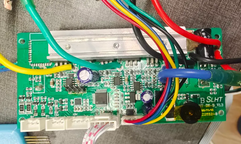
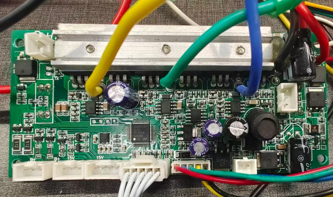
SLHT主板固件下载
//#ifdef MASTER_OR_SINGLE // layout 2.2 has buzzer on the slave board.#define HAS_BUZZER#endif/* GD32F130 48pin possible IO pins:C13 C14 C15 F0 F1 A0 A1 A2A3 A4 A5 A6 A7 B0 B1 B2 B10 B11B12 B13 B14 B15 A8 A9 A10 A11 A12 A13 F6 F7A14 A15 B3 B4 B5 B6 B7 B8 B9mostly used for 6 BLDC mosfet pins: B13 B14 B15 A8 A9 A10mostly used for USART0: B6 B7mostly used for USART1: A2 A3ST-Flash pins: A13 A14 (also used as green and red led on 2.2)so mostly available for other use:C13 C14 C15 F0 F1 A0 A1 A4 A5 A6 A7 B0 B1 B2 B10 B11 B12 A11 F6 F7 A12 A15 B3 B4 B5 B8 B9so available for analog input:A0 A1 A2 A3 A4 A5 A6 A7 B0 B1*/// LED defines - thanks to pacraf, transistors are on led module !#ifdef SLAVE#define LED_GREEN PA12#define LED_ORANGE PA15#define LED_RED PB3#else#define LED_GREEN PB3#define LED_ORANGE PA12 // only two led on the cross-like led panel but users may attach other stuff#define LED_RED PA15#endif#define UPPER_LED PF6 // pacraf: "two line "panel leds goes from PF6. of course via transistor and 1k//#define UPPER_LED PB4 // pacraf: additional outputs on black dupont female header#define LOWER_LED PB5 // pacraf: pulldown, additional outputs on black dupont female header// Mosfet output, little onboard led// #define MOSFET_OUT PF1// Brushless Control DC (BLDC) defines#define BLDC_GH PA10 // green , Tommyboi2001 all bldc pins same as 2.0#define BLDC_GL PB15#define BLDC_BH PA9 // blue#define BLDC_BL PB14#define BLDC_YH PA8 // yellow#define BLDC_YL PB13#define TIMER_BLDC_PULLUP GPIO_PUPD_NONE // robo: not sure if some boards indeed nned GPIO_PUPD_PULLUP like 2.2 or 2.3// Timer BLDC short circuit emergency shutoff define#define TIMER_BLDC_EMERGENCY_SHUTDOWN PB12 // pacraf: smd transistor connected to BRK = PB12. it is NPN type. robo: so pull down = overcurrent// Hall sensor defines//#define HALL_A PA1 // thanks to Tommyboi2001 and pacraf//#define HALL_B PA0//#define HALL_C PB10#define HALL_A PB10#define HALL_B PB2#define HALL_C PB1// GD32F130 USART0 TX/RX: (PA9/PA10)AF1 , (PB6/PB7)AF0 , (PA2/PA3)AF1 , (PA14/PA15)AF1 GD32F130x4 only!#define USART0_TX PB6 // thanks to pacraf#define USART0_RX PB7 // thanks to pacraf// GD32F130 USART1 GD32F130 TX/RX: (PA14/PA15)AF1 , (PA2,PA3)AF1 , (PA8/PB0)AlternateFunction4#define USART1_TX PA2 // thanks to pacraf#define USART1_RX PA3 // thanks to pacraf// 2.10 available for analog input: A4 A6 A7 B0 B1// ADC defines#define VBATT PA4#define ADC_BATTERY_VOLT 0.0171862875#define CURRENT_DC PA5 // robo just guessing#define MOTOR_AMP_CONV_DC_AMP 0.0201465201465// Self hold defines// #define SELF_HOLD PB2 // thanks to pacraf pacraf#define SELF_HOLD PA7// Button defines#define BUTTON PA6 // thanks to pacraf :-)// 2.10 unused/unkown: C13 C14 C15 F0 A4 A5 A6 A7 B0 B1 B11 A11 F7 B8 B9#ifdef HAS_BUZZER// Buzzer defins#define BUZZER PF0#endif//#define CHARGE_STATE TODO_PIN
#define BLDC_BC // old block commutation bldc control// #define BLDC_SINE // silent sine-pwm motor control, added 2025 by Robo Durden.//#define BLDC_SINE_BOOSTER // can boost speed by 15% starting from 87% throttle.#define DRIVING_MODE 0 // 0=pwm, 1=speed in revs/s*1024, 2=torque in NewtonMeter*1024, 3=iOdometer//#define SPEED_AsRevsPerSec // Will overflow at 327 revs/s = 19620 rpm. Hoverboard motor: 14 rpm/V * 50V = 700 rpm#define BAT_CELLS 7 // battery number of cells. Normal Hoverboard battery: 10s//#define BATTERY_LOW_SHUTOFF // will shut off the board below BAT_LOW_DEAD = BAT_CELLS * CELL_LOW_DEAD,#define BATTERY_LOW_BEEP // will start beeping for different battery low lwevels//#define BEEP_BACKWARDS//#define DEBUG_LED // uncomment to activate DEBUG_LedSet(bSet,iColor) macro. iCol: 0=green, 1=organge, 2=red//#define MASTER // uncomment for MASTER firmware.//#define SLAVE // uncomment for SLAVE firmware.#define SINGLE // uncomment if firmware is for single board and no master-slave dual board setup#if defined(MASTER) || defined(SINGLE)// choose only one 'remote' to control the motor//#define REMOTE_DUMMY#ifdef REMOTE_DUMMY#define REMOTE_PERIOD 3 // 3 = 3 seconds period of the zigzag curve//#define TEST_HALL2LED // led the 3-led panel blink according to the hall sensors// #define RTT_REMOTE // log and set via ST-Link dongle// #define WINDOWS_RN // adds a \r before every \n to RTT log#endif//#define REMOTE_UART#define REMOTE_UARTBUS // ESP32 as master and multiple boards as multiple slaves ESP.tx-Hovers.rx and ESP.rx-Hovers.tx#ifdef REMOTE_UARTBUS#define SLAVE_ID 0 // must be unique for all hoverboards connected to the bus#endif//#define REMOTE_CRSF // https://github.com/RoboDurden/Hoverboard-Firmware-Hack-Gen2.x/issues/26//#define REMOTE_ROS2 // https://github.com/RoboDurden/Hoverboard-Firmware-Hack-Gen2.x/issues/122//#define REMOTE_ADC // speed is PA2=TX and steer is PA3=RX of the masterslave header. Get 3.3V from the flash header// DO NOT use the 5V/15V pin of the masterslave header for the potentiometers !!!!!!!!!// SLAVE board has to be connected to the additional UART header, but 5V/15V coming from the masters masterslave header// for calibration, hold the on/off button until the startup melody restarts.// Then release the button and leave the joystick (the two potentiometers) in neutral position.// When the melody returns for 2 seconds, push speed to max.// After another 5 seconds + 2 seconds melody: push speed to min. Then steer to max. Finally steer to min//#define REMOTE_OPTIMIZEPID // will zigzag motor and optimize pid parameters for 1=speed or 3=iOdometer.// monitor with StmStudio/McuViewer or via ST-Link usb dongle RTT and openocd_rtt_32f1x.bat or PlatformIO RTT_Task#ifdef REMOTE_OPTIMIZEPID#define WINDOWS_RN // adds a \r before every \n#endif//#define TEST_HALL2LED // led the 3-led panel blink according to the hall sensors//#define RTT_REMOTE // uncoment for i2c_scanner and dump_i2c_registers to print to rtt :-)// needs either I2C_PB8PB9 or I2C_PB6PB7 and MPU_6050 or MPU_6050old or MPU_6500 or BMI_160 in your defines_2-x-y.h file//#define SEND_IMU_DATA // send the IMU data with RemoteUart or RemoteUartBus. Tested for 2.1.20 !//#define PILOT_USER // uncomment if you want to extend the firmware with custom code :-)//#define PILOT_HOVERBIKE // very experimental pedal detection with chatGpt5 :-/#define SPEED_COEFFICIENT -1 // only used if no PILOT_XY is defined#define STEER_COEFFICIENT 1 // only used if no PILOT_XY is defined//#define DISABLE_BUTTON // this is the opposite of former CHECK_BUTTON define.// remove '//' if you use a slave board as master// or if you turn the boards on/off by injecting a postive voltage into the input pin of the 2pin BUTTON header