 夜雨聆风
夜雨聆风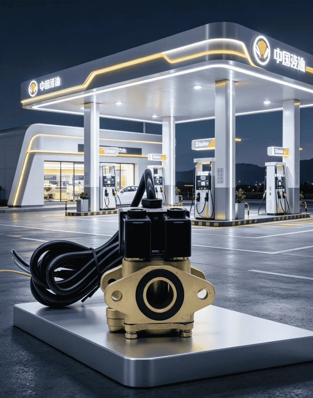
前言
感谢您选用本公司加油机专用双流量防爆电磁阀。本手册适用于全系列结构款式,包含背式、内螺纹、外螺纹、螺法式、双法兰式、直角式六大类型;公称通径涵盖 DN20(6分)、DN25(1‑寸)两种规格,适配各类燃油加油机管路布局与使用场景。请操作人员在正式上岗前通读全文,严格遵循本手册的安装、接线、调试、维保及故障处置规范,可有效保障产品稳定运行、延长使用寿命,同时规避安全风险,确保作业安全合规。
目录
产品概述 主要技术参数 防爆标准与认证说明 产品结构与接口分类 安装操作规范 电气接线说明 日常维护保养规程 常见故障原因以及处置方案 安全操作注意事项 售后说明
1.产品概述
双流量电磁阀是燃油加油机的核心控制元件,主要用于燃油输送管路的通断控制与流量调节。产品采用双线圈先导控制结构,可实现大流量快速供油、小流量精准滴油收尾的双模式切换,有效提升加油计量精度,避免燃油浪费与计量误差。阀体采用隔膜式先导结构,具备动作灵敏、启闭迅速、密封性能优良的特点,可适配燃油介质的长期流通需求;整体采用浇封型防爆结构,符合加油站易燃易爆危险区域的使用要求,能有效抵御油气侵蚀,保障设备运行安全。本产品适配车用汽油、柴油、乙醇汽油等常规燃油介质,适用于各类固定式燃油加油机。
2.主要技术参数
工作介质:车用汽油、柴油、乙醇汽油、甲醇汽油等轻质燃油介质 介质环境温度:‑20℃~+60℃(低温环境需提前确认介质流动性,避免凝固影响阀门动作) 工作油压:0.03MPa‑0.6MPa(超出该压力范围可能导致阀门启闭异常或密封失效) 供电电压:适配加油机常规驱动电压(电压允许偏差±10%,常见AC220V / DC24V) 防爆结构:浇封型 适配通径:DN20、DN25 线圈配置:独立双线圈、内置过热熔断保护 机械启闭寿命:≥100万次
3.防爆标准与认证说明
本系列电磁阀严格按照 IEC60079‑0:2017、IEC60079‑18:2017 国际防爆标准生产制造,满足欧盟ATEX防爆指令2014/34/EU,具备IECEx国际防爆认证,可用于加油站Zone1、Zone2危险防爆区域。电磁线圈整体浇封封装,隔绝油气和带电零部件,禁止私自拆开浇封层,一经破坏防爆性能直接失效。
4.产品结构与接口分类
4.1 零部件构成
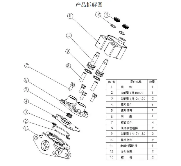
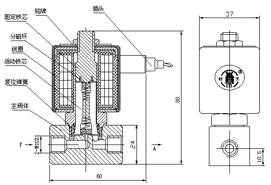
阀体主要由主阀隔膜组件、先导阀芯、双电磁线圈、阀盖、密封垫片、进出油接口构成。
4.2 六种接口类型
背式:底座固定、下出油,加油机内置安装 内螺纹:阀口内置螺纹,油管接头拧入 外螺纹:阀体两端外牙,螺母锁紧管路 螺法式:一端螺纹、一端法兰,适配混合管路 双法兰式:两端法兰高压密封 直角式:90°L型流道,管路转向安装
5.安装操作规范
安装之前检查阀体外观,壳体无磕碰裂痕、密封配件齐全,线圈外壳不存在破损开裂,核对通径、接口型号。 阀体流向跟随阀体箭头标识;优先竖直安装;卧式安装线圈朝上,杜绝线圈浸泡油污。 安装前冲洗管路,清除铁屑、杂质,防止卡滞先导阀芯。 法兰、螺纹位置加装密封垫片,螺栓对角分次锁紧,防止垫片偏移渗油;螺纹接口缠绕耐油生料带。 防爆接线腔做好防水防尘;接地线可靠连接,接地电阻≤0.1Ω,满足场站防爆规范。
6.电气接线说明
6.1 端子‑线色标准
公共负极(COM):黑色 大流量线圈(主阀开启):红色 小流量线圈(精准慢出油):黄色 接地保护地线:黄绿双色
6.2 简易接线原理图
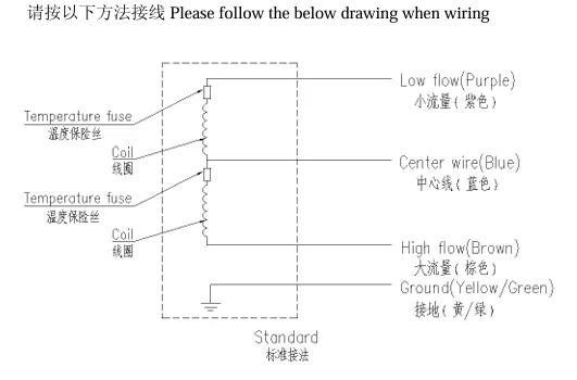
【防爆电磁阀接线盒内部:大流量线圈、小流量线圈两个独立绕组】
6.3 接线逻辑讲解
内置两组独立电磁线圈:红线=高速大流量供油;黄线=低速收尾小流量;黑线为两个线圈共用公共负极。 通电逻辑:加油前期红线通电,阀门全开大流量出油;油量临近设定数值,红线断电、黄线通电,切换小流量慢出油,保证计量精准。 定制版本引脚标识以线圈外壳刻印字符为准(COM‑公共端、H‑大流量、L‑小流量、PE‑接地)。
6.4 接线作业规范
接线前关闭加油机总电源,禁止带电施工。 严格对照线缆色标接线,大小流量控制线禁止混接、错接。 接线端子压紧牢固,铜线无裸露;锁紧接线盒密封螺丝,阻隔油气进入腔体。 电源线预留松弛余量,避开高温管道、锋利边角,防止阀体震动拉扯断线。 电源回路加装适配熔断器:AC220V选用100mA保险丝;DC24V选用500mA保险丝。
7.日常维护保养规程
每月开展一次阀门启闭测试,来回切换大小流量档位,确认阀芯动作顺畅、流量切换正常。 日常巡检:接线端子松紧、油路渗漏、阀体启闭噪音、线圈外壳表面温度。 油气浓度高、腐蚀性强的站点缩短巡检周期,重点检查浇封线圈外壳、各个密封面。 防爆浇封线圈禁止撬开改装;外壳破损必须整体更换原厂总成。 设备长期停机重启前疏通管路、复查接线和接地,空载通电测试启闭。 拆解清洗阀芯时依次摆放零件,隔膜、节流小孔薄片禁止划伤、挤压变形。
8.常见故障以及处置方案
9.安全操作注意事项
本品属于防爆零部件,加油站易燃易爆区域禁止私自拆装、改造阀体结构,所有作业遵守加油站安全管理条例。 禁止超压、超介质温度、超额定电压运行,避免零件损坏引发安全隐患。 维修配件只允许选用原厂零件;非标配件会破坏密封性和防爆性能。 运行期间出现异响、渗油、线圈异常发烫,立刻切断电源停机检修。 报废线圈、废旧零部件按照危险废弃物标准处置,不可随意丢弃,防止土壤、油气环境污染。 线圈灰尘采用湿布擦拭,禁止干擦摩擦起静电。
10.售后说明
安装、使用过程出现故障优先对照故障表排查;无法自行处理可联系厂家技术人员上门检修。 人为损坏、杂质堵塞、私自拆解、非原厂配件造成故障不在保修范围;其余故障遵照产品保修条款执行。
浙江奥博科技有限公司地址:浙江省温州市温州海洋经济发展示范区昆鹏街道雁云路 706 号 温州文博科技产业园 9 幢 102 室联系电话:13957758609官方网址:WZQD.COM
Operation Manual for Full‑Series Dual‑Flow Solenoid Valve of Fuel Dispenser
Preface
Thank you for purchasing our explosion‑proof dual‑flow solenoid valve specially matched for fuel dispensers. This manual applies to all structural types including back‑mounted, internal‑thread, external‑thread, screw‑flange, double‑flange and right‑angle styles. Two nominal diameters DN20 (3/4‑inch) and DN25 (1‑inch) are available to fit pipeline layouts of various fuel dispensers.
All operators shall read through this manual before operation. Please strictly abide by the specifications for installation, wiring, commissioning, maintenance and troubleshooting. Proper operation guarantees stable service, prolonged service life and eliminates potential safety risks at fuel‑filling stations.
Table of Contents
Product Overview Main Technical Parameters Explosion‑proof Standards and Certification Product Structure and Port Classification Installation Specifications Electrical Wiring Instructions Routine Maintenance Regulations Common Faults and Troubleshooting Solutions Safety Operation Notes After‑sales Instructions
1. Product Overview
The dual‑flow solenoid valve acts as the core control component for fuel dispensers, responsible for pipeline on‑off control and flow adjustment. Adopting a dual‑coil pilot‑operated structure, it switches between high‑speed large‑flow fuel supply and low‑flow precise cut‑off. This design greatly improves metering accuracy, reduces fuel waste and measurement deviation.
The main valve adopts a diaphragm pilot structure featuring sensitive response, fast switch‑over and outstanding sealing performance. The whole coil assembly is potted for explosion‑proof performance to resist fuel‑gas corrosion and satisfy hazardous‑zone requirements of petrol stations. It is compatible with gasoline, diesel, ethanol‑blended gasoline, methanol‑blended gasoline and other light‑duty fuels for stationary fuel dispensers.
2. Main Technical Parameters
Working Medium: Gasoline, diesel fuel, ethanol‑gasoline, methanol‑gasoline and other light fuels Ambient Medium Temperature: ‑20℃ ~ +60℃. Keep fuel fluidity under low‑temperature conditions to avoid valve jamming Working Oil Pressure: 0.03MPa‑0.6MPa. Excessive pressure may trigger sealing failure and abnormal switching Rated Supply Voltage: Standard driving voltage for dispensers, allowable tolerance ±10% (common AC220V / DC24V) Explosion‑proof Type: Potted encapsulation Nominal Sizes: DN20, DN25 Coil Configuration: Two independent coils with built‑in over‑heat fuse‑out protection Mechanical Switch‑over Lifespan: ≥1 000 000 cycles
3. Explosion‑proof Standards and Certification
This series of solenoid valves is manufactured in compliance with international explosion‑proof standards IEC60079‑0:2017 and IEC60079‑18:2017. It meets EU ATEX directive 2014/34/EU and has obtained valid IECEx international explosion‑proof certification for Zone 1 and Zone 2 hazardous locations of filling stations.
Electrical components of coils are fully sealed by potting compound to isolate flammable oil‑gas. Never dismantle the encapsulated layer; otherwise explosion‑proof capability will be permanently invalidated.
4. Product Structure and Port Classification
4.1 Main Components
Main‑valve diaphragm assembly, pilot spool, dual electromagnetic coils, valve cover, sealing gaskets, inlet and outlet ports.
4.2 Six Kinds of Connection Ports
Back‑mounted Type: Fixed base, downward oil outlet, built‑in installation inside dispenser cabinet Internal‑thread Type: Female thread on ports for direct joint screwing External‑thread Type: Male thread ends, fastened by pipeline lock nuts for quick replacement Screw‑flange Composite Type: One threaded end and one flange end for mixed‑layout pipelines Double‑flange Type: Flange‑to‑flange connection with high‑pressure flat‑face sealing Right‑angle Type: 90‑degree L‑shaped runner for pipeline turning layout
5. Installation Specifications
Inspect the valve body before installation: no shell cracks, complete sealing accessories and intact coil housing. Confirm port style and nominal size match the dispenser pipeline. Install in accordance with the flow arrow printed on the housing. Vertical mounting is preferred. For horizontal installation, arrange the coil upward to prevent oil contamination. Flush pipelines thoroughly prior to installation to clear iron scraps and debris which may jam the pilot spool. Fit sealing gaskets for flange and threaded joints. Fasten flange bolts diagonally and evenly. Wrap oil‑resistant PTFE tape on threaded connections. Keep the wiring cavity waterproof and dust‑proof in explosion‑risk zones. Install reliable earthing with earth‑loop resistance ≤0.1Ω to meet station safety codes.
6. Electrical Wiring Instructions
6.1 Standard Wire‑Colour Definition
Common Negative (COM): Black Large‑flow Coil (Full‑open Main Valve): Red Small‑flow Coil (Precise Slow‑flow): Yellow Protective Earth Wire: Green‑Yellow Bicoloured
6.2 Text‑Based Wiring Schematic
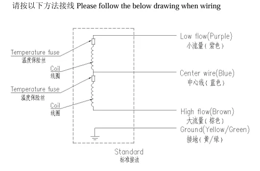
【防爆电磁阀接线盒内部:大流量线圈、小流量线圈两个独立绕组】
6.3 Working Logic
Two separate coils are equipped inside the valve. The red wire controls high‑speed large‑flow fuel delivery at the early filling stage. When reaching the preset fuel volume, red‑wire power cuts off and the yellow‑wire coil energises to activate low‑speed trickle‑flow for high‑precision metering.For custom‑made versions, terminal labels (COM / H‑High flow / L‑Low flow / PE‑Earth) marked on the coil shell shall prevail.
6.4 Wiring Operation Rules
Cut off the main power supply of the fuel dispenser before wiring. Never perform live‑wire operation. strictly follow the colour code. Do not swap large‑flow and small‑flow control cables. Fasten terminal screws tightly with no exposed copper conductor. Lock the terminal‑box sealing screws to block flammable vapour. Leave slack allowance on power cables. Keep wires far away from high‑temperature pipes and sharp metal edges to avoid vibration‑caused wire breakage and insulation damage. Install matched fuses on power circuits: 100 mA fuse for AC220V coils; 500 mA fuse for DC24V coils.
7. Routine Maintenance Regulations
Execute switch‑over test every month. Toggle high/low flow modes to verify smooth spool movement and stable flow switching. Daily inspection checklist: terminal tightness, pipeline leakage, abnormal operating noise and coil‑shell surface temperature. Shorten inspection cycles for stations with heavy oil‑gas and corrosive atmosphere. Prioritise encapsulated coil housing and all sealing surfaces. Do not pry open or refit explosion‑proof encapsulated coils. Replace the whole original coil assembly when housing gets damaged. Clear pipeline obstructions, inspect wiring integrity and earthing status before restarting after long‑time shutdown. Carry out no‑load switch‑over test. Take apart and clean spool components in sequence. Prevent scratches and deformation on diaphragms and throttle orifice sheets.
8. Common Faults and Troubleshooting
9. Safety Operation Notes
This product belongs to explosion‑proof hardware. Do not disassemble or reconstruct the valve body inside petrol‑station hazardous zones. Comply fully with petrol‑station safety codes. Never operate beyond rated pressure, temperature and voltage limits, which may trigger component breakdown and explosion‑proof failure. Only original factory spare parts are permitted for maintenance. Non‑standard accessories impair sealing and explosion‑proof properties. Cut off power supply and halt operation immediately upon abnormal noise, fuel leakage or over‑heated coils. Resume service only after troubleshooting. Disposed coils and scrap parts shall be handled as hazardous waste, random dumping is forbidden to avoid environmental contamination. Clean coil dust with damp cloth. Dry‑wiping is prohibited to avoid static‑electric sparks.
10. After‑sales Instructions
Refer to the fault‑checking table first when breakdowns occur. Contact factory technicians for on‑site maintenance for unsolvable failures. Damage caused by human operation, sediment clogging, unauthorised disassembly and non‑original spare‑part adoption is excluded from warranty coverage. All other defects are covered under official warranty terms.
Zhejiang Aobo Technology Co., Ltd.Address: Room 102, Building 9, Wenzhou Wenbo Science and Technology Industrial Park, No.706 Yanyun Road, Kunpeng Street, Wenzhou Marine‑economic Development Demonstration Zone, Wenzhou City, Zhejiang Province, P.R.ChinaMobile: +86‑13957758609Official Website: WZQD.COM