 夜雨聆风
夜雨聆风概述
坐标一致性是地理空间数据处理中的关键概念,它确保不同数据源、不同处理步骤之间的空间参考系统保持一致,从而保证空间分析和处理结果的准确性。GeoAI 项目实现了多种坐标一致性处理方法,包括坐标系统转换、边界框转换、地理变换管理等,广泛应用于数据预处理、模型训练和推理过程中。
主要特点
• 多坐标系支持:支持多种坐标参考系统 (CRS),包括 WGS84、UTM 等 • 自动坐标转换:在不同坐标系之间自动进行转换 • 地理变换管理:维护和更新地理变换信息 • 边界框转换:支持在不同坐标系之间转换边界框 • 广泛的应用场景:适用于数据预处理、模型训练、推理等多种场景
坐标一致性基本原理
1. 基本概念
坐标参考系统 (CRS):定义了如何将地球表面的点映射到二维平面的系统,包括地理坐标系和投影坐标系。
地理变换:描述了如何将像素坐标转换为地理坐标的数学关系。
坐标一致性:确保不同数据源、不同处理步骤使用相同的坐标参考系统,或在需要时进行正确的转换。
2. 工作流程
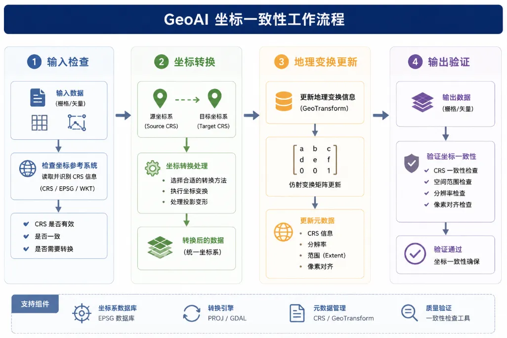
3. 坐标转换方法
• 边界框转换:将一个坐标系中的边界框转换为另一个坐标系 • 矢量数据转换:将矢量数据从一个坐标系转换为另一个坐标系 • 栅格数据转换:将栅格数据从一个坐标系重投影到另一个坐标系
GeoAI 中的坐标一致性实现
GeoAI 项目在多个模块中实现了坐标一致性技术,主要包括:
1. 核心功能
• 坐标系统管理:通过 rasterio和geopandas管理坐标参考系统• 坐标转换:通过 rasterio.warp和geopandas.to_crs实现坐标转换• 边界框转换:通过 rasterio.warp.transform_bounds实现边界框转换• 地理变换管理:通过 rasterio.transform管理地理变换
2. 应用场景
• 数据预处理:确保输入数据的坐标一致性 • 模型训练:确保训练数据和标签的坐标一致性 • 模型推理:确保输入和输出的坐标一致性 • 数据融合:确保不同数据源的坐标一致性
3. 核心功能
核心代码分析
1. 边界框转换
功能:在 clip_raster_by_bbox 函数中,支持将边界框从一个坐标系转换到另一个坐标系。
代码分析:
defclip_raster_by_bbox( input_raster: str, output_raster: str, bbox: List[float], bands: Optional[List[int]] = None, bbox_type: str = "geo", bbox_crs: Optional[str] = None,) -> str:# ... 其他代码 ...# Open the source rasterwith rasterio.open(input_raster) as src:# Get the source CRS src_crs = src.crs# Handle different bbox typesif bbox_type == "geo": minx, miny, maxx, maxy = bbox# Validate geographic bboxif minx >= maxx or miny >= maxy:raise ValueError("Invalid geographic bbox. Expected (minx, miny, maxx, maxy) where minx < maxx and miny < maxy" )# If bbox_crs is provided and different from the source CRS, transform the bboxif bbox_crs isnotNoneand bbox_crs != src_crs:try:# Transform bbox coordinates from bbox_crs to src_crs minx, miny, maxx, maxy = transform_bounds( bbox_crs, src_crs, minx, miny, maxx, maxy )except (ValueError, RuntimeError) as e:raise ValueError(f"Failed to transform bbox from {bbox_crs} to {src_crs}: {str(e)}" )# Calculate the pixel window from geographic coordinates window = src.window(minx, miny, maxx, maxy)# Use the same bounds for the output transform output_bounds = (minx, miny, maxx, maxy)# ... 其他代码 ...代码说明:
• 打开源栅格文件,获取其坐标参考系统 (CRS) • 如果提供了边界框的 CRS 且与源 CRS 不同,使用 transform_bounds函数将边界框转换到源 CRS• 计算转换后的边界框对应的像素窗口 • 使用转换后的边界框计算输出栅格的地理变换
2. 矢量数据坐标转换
功能:在 vector_to_raster 函数中,支持将矢量数据从一个坐标系转换到另一个坐标系。
代码分析:
defvector_to_raster( vector_path: Union[str, gpd.GeoDataFrame], output_path: Optional[str] = None, reference_raster: Optional[str] = None, attribute_field: Optional[str] = None, output_shape: Optional[Tuple[int, int]] = None, transform: Optional[Any] = None, pixel_size: Optional[float] = None, bounds: Optional[List[float]] = None, crs: Optional[str] = None, all_touched: bool = False, fill_value: Union[int, float] = 0, dtype: Any = np.uint8, nodata: Optional[Union[int, float]] = None, plot_result: bool = False,) -> np.ndarray:# ... 其他代码 ...# Reproject vector data if its CRS doesn't match the output CRSif gdf.crs != crs: logger.info("Reprojecting vector data from %s to %s", gdf.crs, crs) gdf = gdf.to_crs(crs)# ... 其他代码 ...代码说明:
• 加载矢量数据,获取其坐标参考系统 (CRS) • 检查矢量数据的 CRS 是否与目标 CRS 一致 • 如果不一致,使用 to_crs方法将矢量数据转换到目标 CRS• 继续处理转换后的矢量数据
3. 地理变换计算
功能:在 clip_raster_by_bbox 函数中,计算裁剪后栅格的新地理变换。
代码分析:
defclip_raster_by_bbox( input_raster: str, output_raster: str, bbox: List[float], bands: Optional[List[int]] = None, bbox_type: str = "geo", bbox_crs: Optional[str] = None,) -> str:# ... 其他代码 ...# Calculate new transform for the clipped raster new_transform = from_bounds( output_bounds[0], output_bounds[1], output_bounds[2], output_bounds[3], window_width, window_height, )# Create a metadata dictionary for the output out_meta = src.meta.copy() out_meta.update( {"height": window_height,"width": window_width,"transform": new_transform,"count": len(bands_to_read), } )# ... 其他代码 ...代码说明:
• 使用 from_bounds函数,根据输出边界、宽度和高度计算新的地理变换• 更新输出栅格的元数据,包括新的地理变换 • 确保输出栅格的坐标信息正确
4. 坐标一致性在分块推理中的应用
功能:在 predict_geotiff 函数中,确保分块推理过程中的坐标一致性。
代码分析:
defpredict_geotiff( model: "torch.nn.Module", input_raster: str, output_raster: str, tile_size: int = 256, overlap: int = 64, batch_size: int = 4, input_bands: Optional[List[int]] = None, num_classes: int = 1, output_dtype: str = "float32", output_nodata: float = -9999.0, blend_mode: Union[str, BlendMode] = "spline", blend_power: int = 2, tta: bool = False, preprocess_fn: Optional[Callable[..., np.ndarray]] = None, postprocess_fn: Optional[Callable[..., np.ndarray]] = None, device: Optional[str] = None, compress: str = "lzw", verbose: bool = True,) -> str:# ... 其他代码 ...with rasterio.open(input_raster) as src: height = src.height width = src.width profile = src.profile.copy()# ... 其他代码 ...# 构建瓦片网格 tiles: List[Tuple[int, int, int, int]] = []for row inrange(0, height, stride):for col inrange(0, width, stride): row_end = min(row + tile_size, height) col_end = min(col + tile_size, width)# 调整起始位置,确保瓦片大小 row_start = max(0, row_end - tile_size) col_start = max(0, col_end - tile_size) tiles.append((row_start, col_start, row_end, col_end))# ... 其他代码 ...# 写入输出 output_dir = os.path.dirname(os.path.abspath(output_raster))if output_dir: os.makedirs(output_dir, exist_ok=True) out_count = output_array.shape[0] if output_array.ndim == 3else1 profile.update( count=out_count, dtype=output_dtype, nodata=output_nodata, compress=compress, )with rasterio.open(output_raster, "w", **profile) as dst:if output_array.ndim == 3:for band_idx inrange(out_count): dst.write(output_array[band_idx].astype(output_dtype), band_idx + 1)else: dst.write(output_array.astype(output_dtype), 1)# ... 其他代码 ...代码说明:
• 打开输入栅格文件,获取其元数据和地理变换 • 构建瓦片网格,确保每个瓦片的坐标正确 • 处理每个瓦片,保持其空间参考 • 写入输出栅格时,使用原始栅格的元数据,确保坐标一致性
使用示例
示例 1:使用不同坐标系的边界框裁剪栅格
import geoai# 输入和输出路径input_path = "path/to/input.tif"# 假设输入栅格使用 UTM 坐标系output_path = "path/to/output_clipped.tif"# 定义 WGS84 坐标系的边界框bbox = (-122.5, 37.7, -122.4, 37.8) # 经纬度坐标# 裁剪栅格数据,自动转换坐标系clipped_path = geoai.clip_raster_by_bbox( input_raster=input_path, output_raster=output_path, bbox=bbox, bbox_crs="EPSG:4326"# 明确指定边界框的坐标系)print(f"裁剪完成,结果保存到: {clipped_path}")示例 2:将矢量数据转换到目标坐标系
import geoaiimport geopandas as gpd# 加载矢量数据gdf = gpd.read_file("path/to/vector.shp") # 假设矢量数据使用 WGS84 坐标系# 目标坐标系(UTM 区域 10N)target_crs = "EPSG:32610"# 转换矢量数据到目标坐标系gdf_transformed = gdf.to_crs(target_crs)# 保存转换后的数据gdf_transformed.to_file("path/to/vector_utm.shp")print("矢量数据转换完成!")# 将转换后的矢量数据栅格化raster_output = "path/to/rasterized.tif"geoai.vector_to_raster( vector_path=gdf_transformed, output_path=raster_output, pixel_size=1.0, bounds=gdf_transformed.total_bounds, crs=target_crs)print("矢量数据栅格化完成!")示例 3:确保多数据源的坐标一致性
import geoaiimport geopandas as gpd# 加载影像数据image_path = "path/to/satellite.tif"# 加载矢量数据(不同坐标系)vector_path = "path/to/buildings.geojson"# WGS84 坐标系gdf = gpd.read_file(vector_path)# 读取影像的坐标系with geoai.utils.raster.read_raster_metadata(image_path) as meta: image_crs = meta.crs# 转换矢量数据到影像的坐标系if gdf.crs != image_crs:print(f"转换矢量数据从 {gdf.crs} 到 {image_crs}") gdf = gdf.to_crs(image_crs)# 导出训练数据,确保坐标一致性training_output = "path/to/training_data"geoai.export_geotiff_tiles( in_raster=image_path, out_folder=training_output, in_class_data=gdf, tile_size=256, stride=128)print("训练数据导出完成!")示例 4:使用坐标一致性进行空间分析
import geoaiimport geopandas as gpd# 加载两个不同坐标系的矢量数据gdf1 = gpd.read_file("path/to/data1.shp") # WGS84gdf2 = gpd.read_file("path/to/data2.shp") # UTM# 确保坐标一致性:将 gdf2 转换到 gdf1 的坐标系gdf2_transformed = gdf2.to_crs(gdf1.crs)# 执行空间分析:计算两个数据集的交集intersection = gpd.overlay(gdf1, gdf2_transformed, how='intersection')# 保存结果intersection.to_file("path/to/intersection.shp")print("空间分析完成!")坐标一致性是 GeoAI 项目中处理地理空间数据的关键技术,它确保不同数据源、不同处理步骤之间的空间参考系统保持一致,从而保证空间分析和处理结果的准确性。GeoAI 实现了多种坐标一致性处理方法,包括坐标系统转换、边界框转换、地理变换管理等,广泛应用于数据预处理、模型训练和推理过程中。
通过合理选择坐标系统、正确进行坐标转换、有效管理地理变换,可以显著提高地理空间数据处理的效率和准确性。本文档详细介绍了坐标一致性的基本原理、实现方法和应用场景,帮助用户快速理解和使用坐标一致性技术,为各种地理空间应用提供有力支持。