ARTICLE · 1227811
太阳能潜水泵安装完全指南:分步流程与接线图
太阳能潜水泵安装完全指南
分步流程与接线图
技术安装指南 · 离网供水系统 · 阅读约 15 分钟
太阳能潜水泵只靠光伏板就能从管井里抽水,无需市电。本文从现场勘测一直讲到出稳定水:怎么算系统、怎么架板接线、怎么安全下泵、怎么调试验收,以及日常维护。内容结合通用安装惯例和相关电气、水泵标准。
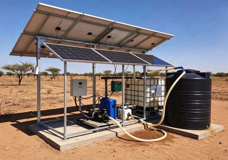
完整的离网太阳能抽水系统:光伏阵列、管井井房和出水。
📌 一句话结论
先勘测水井,算出总动扬程 TDH 和日需水量,再按泵功率 × 1.3–1.5 配置光伏板。面板朝赤道、按纬度角架设,串联后经直流断路器和防雷器接到控制器 P+/P− 端子。扬水管上装止回阀,泵电缆压接+热缩处理,每 3 m 绑在扬水管上,下泵深度为动水位以下 5–10 m、井底以上至少 5 m。封井口、排气、对照泵曲线测流量和压力。潜水泵系统的电缆压降要控制在 3% 以内,绝不能空转。
1. 安装前:先选型再买货
选型是后期无法便宜返工的一步。两个数字决定整个设计:日需水量和总动扬程(TDH)。
1.1 读懂水井
- 井深与井径
——多数潜水泵要 4 英寸(100 mm)井孔;紧凑型 3 英寸泵可装更小的井。 - 静水位(SWL)
——地面到静止水面的距离。 - 动水位(DWL)
——抽水时水位下降多少(按 10–30% 降深预留)。 - 井出水量
——管井可持续供应的升/小时;选型绝不能超过这个值。 - 水质
——记录 TDS、pH 和含砂量;这些决定过流部件材质和泵型。
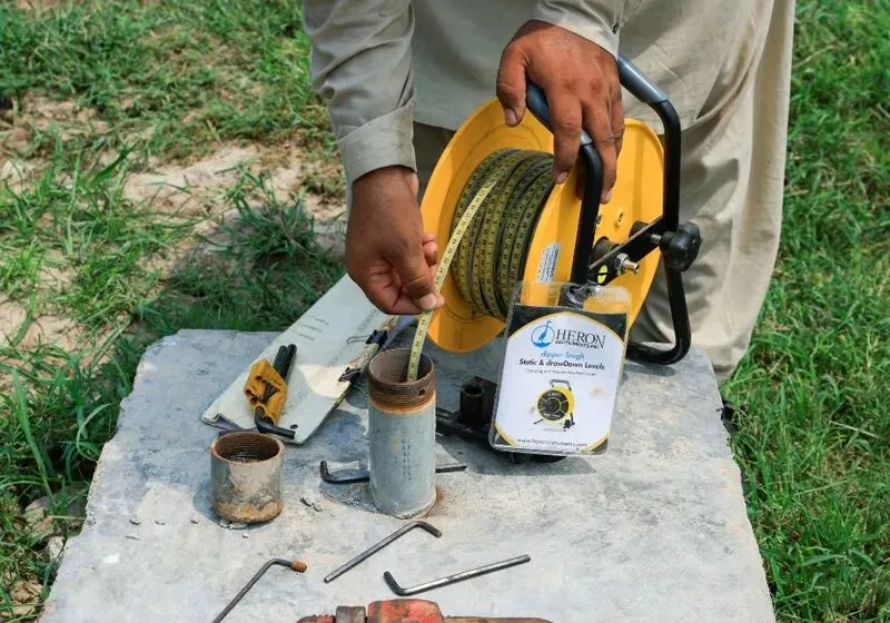
现场勘测:选泵前先测静水位和动水位。
1.2 计算日需水量
1.3 计算总动扬程(TDH)
1.4 配置光伏阵列
1.5 面板布置
朝赤道(北半球朝南,南半球朝北)。 倾角接近纬度(季节可调 ±15°);上午 9 点到下午 3 点之间不能有遮阴。 电缆尽量短(50 m 以内);安装高度高于当地积雪/积沙线,并满足抗风载荷。
2. 工具与材料
必备工具
- 电工类:
万用表、非接触验电笔、钳形表、剥线钳、绝缘螺丝刀(600 V)、压接钳、热风枪。 - 机械类:
管钳(12/18 英寸)、活动扳手、切管器/去毛刺器、生料带、卷尺、水平尺。 - 专用类:
测深锤、流量计或标定水桶、压力表、三脚架绞车和安全绳、pH/TDS 笔。
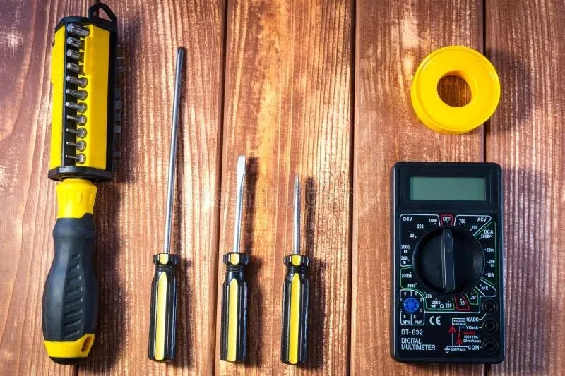
开工前铺好必备电工和机械工具。
材料与部件
按 TDH 和流量选好的泵;MPPT 太阳能泵控制器;潜水泵专用电缆。 光伏板;支架;MC4 接头和抗紫外光伏电缆;多串时用带熔断器的汇流箱。 扬水管(HDPE/PVC)、止回阀、扭矩限制器和不锈钢安全绳、井口卫生密封。 直流断路器和熔断器、Type-2 防雷器(SPD)、IP65 以上接线盒、电缆格兰头、2.4 m 铜接地极。 选配:压力罐、浮球/水位传感器(缺水保护)、蓄水池、远程监控。
3. 安全与标准
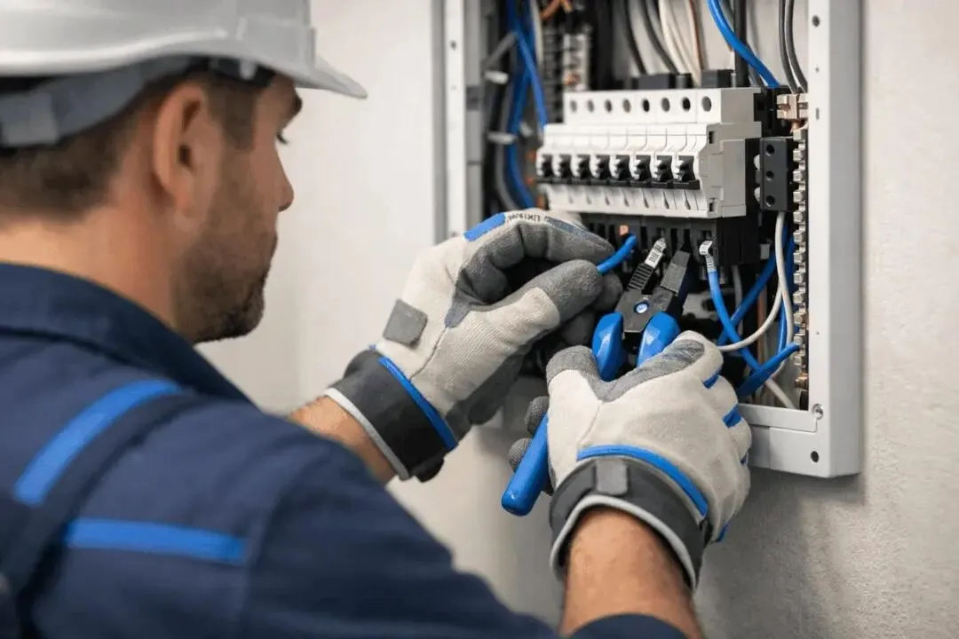
电气安全:绝缘手套、非接触验电、可靠接地。
必须要求的认证
向供应商要真实证书编号,不能只看 Logo。
4. 分步安装
1架设并接线光伏阵列
面板朝赤道、接近纬度角固定在混凝土墩或地桩上,按当地抗风设计。支架用 6–10 AWG 铜线接到 2.4 m 接地极。面板串联直到 Voc 落在控制器直流输入范围内;较大阵列用多串并联并经过带熔断器的汇流箱。用万用表核对 Voc 和极性。
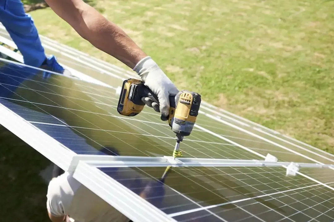
阵列装在接地、抗风的地面支架上朝太阳。
2安装控制器与保护
MPPT 控制器装在阴凉、通风、IP65/NEMA 4X 防护箱内,四周留 15 cm 散热间隙。光伏输入端装直流断路器(额定电流为短路电流的 125%)和 Type-2 SPD,两者都接地。抗紫外光伏电缆穿管敷设,保持大弯径,每个入口装格兰头。
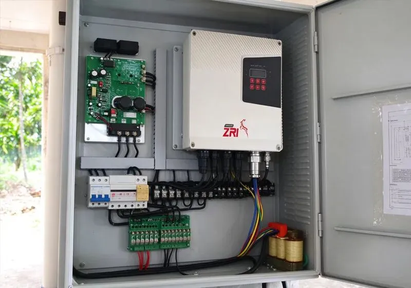
MPPT 控制器装在阴凉通风的防水箱内,配直流断路器和防雷器。
3做电气连接
断路器断开、面板盖住后:串接接 PV+/PV−,电机电缆接控制器输出(三相为 U/V/W),水位/浮球传感器接保护输入。端子按力矩拧紧并拉扯测试。接地连续性确认小于 1 Ω。
4地表预处理泵体
泵出口装止回阀(箭头朝上)。泵电缆用带胶热缩管+压接套管处理,从中间往两端加热。安全绳挂在吊环上——绝不能挂在动力电缆上。潜水泵电缆每 3 m 绑在扬水管上,留少量余量。
5把泵下到井里
两人配合;绞车绳绑在安全绳上。缓慢下放,逐节接扬水管。当泵位于动水位以下 5–10 m、井底以上至少 5 m 时停。安全绳和扬水管分别独立固定在井口,装卫生井口密封,电缆穿格兰头。
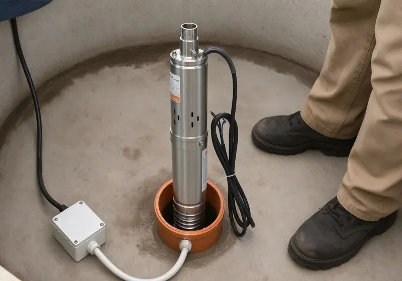
用三脚架绞车下放泵,连同安全绳和扬水管一起下到设计深度。
6排气、调试与测试
设定控制器参数(泵电压、缺水延时、压力设定点)。揭开面板、半关出水阀后合断路器。应听到轻微嗡鸣,1–5 分钟内出水。缓慢开阀防水锤。测流量和压力,与泵曲线对比。
5. 接线图
各品牌端子标号不同(P+/P−、PV+/PV−、U/V/W)——以厂家手册为准。图 1 是标准功率路径;图 2 增加水箱水位控制。
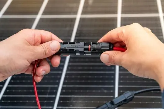
整齐、带标签的串联接线:面板端用带胶热缩处理并贴极性标签。
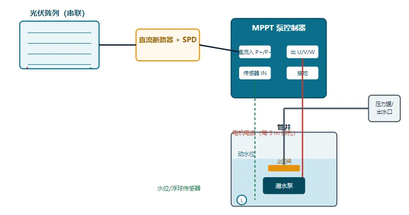
图 1——基本直流系统:串联光伏阵列 → 直流断路器 + SPD → MPPT 控制器 → 潜水泵,配止回阀和缺水传感器。
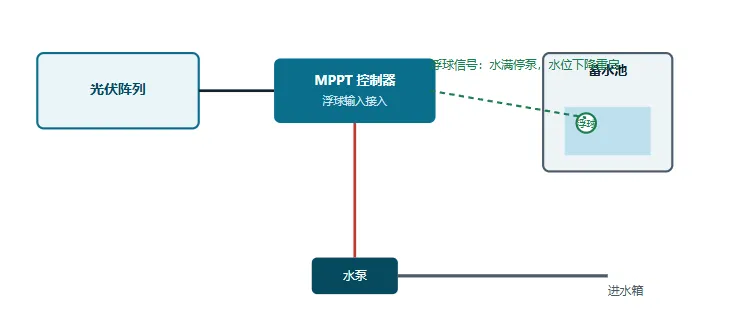
图 2——水箱水位控制:浮球开关在水满时通知控制器停泵,水位下降后自动重启。白天抽水存起来,就不需要蓄电池。
6. 电缆选型(压降控制在 3% 以内)
电缆太细会让电机"吃不饱"并触发控制器保护。以厂家表为主;下表是按系统电压和单程距离的起步参考。
7. 调试验收清单
- 电气:
Voc 在板厂标称 ±5% 以内;极性正确;接地电阻 < 1 Ω;绝缘 > 1 MΩ;带载时控制器不烫手。 - 水力:
在实测 TDH 下流量为额定值的 85–105%(桶测:L/h = 升数 × 3600 ÷ 秒数);压力稳定;止回阀止水;无渗漏。 - 基线:
记录日期、天气、流量、电压、电流、压力——这是日后排查的对照。
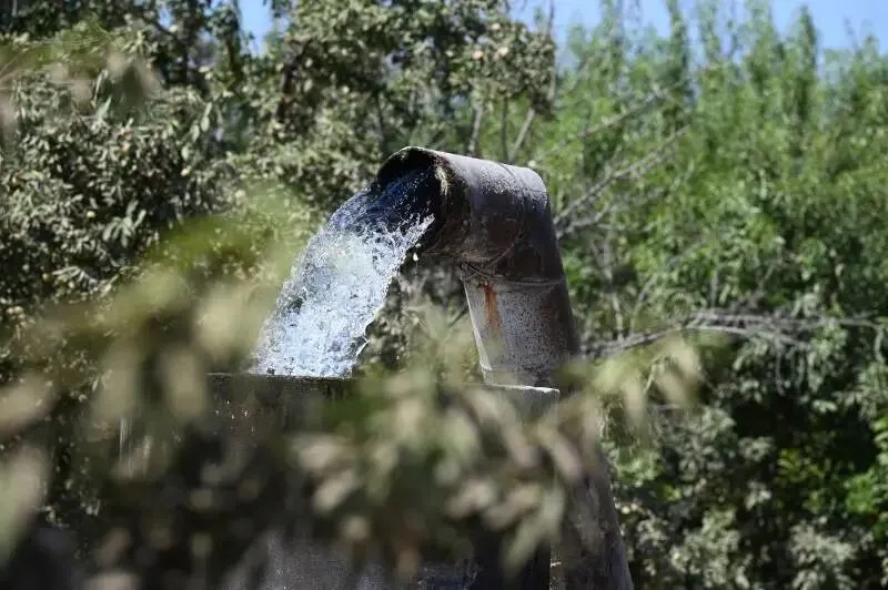
调试:往蓄水池注水时对照泵曲线核对流量与压力。
8. 常见故障排查
泵不启动
测控制器输入端光伏电压(偏低说明遮阴/积灰/一串断开)。读控制器故障码。断开泵,测绕组电阻——开路是电缆/电机断路,接近 0 是绕组短路。确认缺水传感器没有误触发。
流量偏低
重测 TDH(实际降深常大于估计)。检查止回阀是否堵塞、出水阀是否全开。测泵端电压——低于额定 90% 多半是电缆太细、压降过大。听出口有无气声(进水口以上有漏点会进气)。
频繁启停
通常是井供不上:降流量或加蓄水。再检查间歇遮阴、接头松动/腐蚀、控制器日志里的过温/过压事件。
水浑浊或带泥
新装后短暂浑浊正常,约 30 分钟自清。持续浑浊说明泵离井底太近(上提 5–10 m)或流量抽起泥沙(限流、加 5–20 µm 过滤器)。
电机转但不出水
失吸(进水口露出水面)、止回阀卡开、扬水管裂漏回、或三相泵反转(调换两相)。看电流——反转泵电流明显偏小。
电流偏高
机械卡阻(轴承磨损、叶轮擦壳、异物)、实际扬程高于设计、或接头电阻过大发热。用钳形表对照数据表;机械问题就提泵检修。
9. 维护计划
- 每月:
清洗面板、桶测流量、查漏、记录电压电流。积灰面板可损失 20–30% 出力。 - 每季度:
水质检查、查接头和接地、试止回阀、测静水位。 - 每年:
完整电气测试(绝缘电阻)、板输出检测、复紧支架和端子、查控制器有无虫患/受潮、复盘日志。 - 按需:
高硬度/高 TDS 水每几年给止回阀和泵除垢;流量下降时检修或换泵。
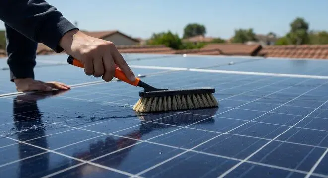
日常维护:清洗面板——积灰阵列可损失 20–30% 出力。
10. 常见问题
Q1. 太阳能潜水泵能抽多深?
常规 DC 泵 30–120 m;高扬程和三相 AC/变频系统 200–300 m。极限取决于电机功率、级数、所需流量和电缆压降——流量越小扬程越高。
Q2. 可以自己装吗?
浅井(<30 m)和小功率(<750 W)DC 系统通常可以 DIY。深井、大功率或三相系统、饮用水工程应由持证承包商安装或验收,尤其是当地要求执照的地区。
Q3. 需要多大阵列?
泵功率 × 1.3–1.5 扣损失——1,500 W 泵约需 2,000–2,250 Wp。再用每日 Wh 除以当地峰值日照和 0.8 效率校验运行时间。
Q4. 阴天能用吗?
能用但流量下降——MPPT 控制器按可用功率降速,阴天约为额定 25–70%。阵列过配 30–50% 并蓄 2–5 天水应对连阴天。
Q5. 空转会怎样?
电机失去水冷,几分钟内损坏——密封、轴承、绕组全毁。控制器缺水输入接水位传感器、加上正确下泵深度即可避免;传感器只占换泵费用的零头。
Q6. 能供饮用水吗?
可以,但需 NSF/ANSI 61 部件、饮用水级管路、卫生井口密封,并按水质化验做过滤、UV 等处理。
Q7. 冬天怎么防冻?
管路可能结冰的地方把地表管埋到冻土层以下或加伴热带;季节性停机时把地表水排空、压缩空气吹净管路,面板仰角加大以自洁积雪。泵本身在冻土层以下,受土层保护。
结语
太阳能潜水泵在入水前就决定了成败:按 TDH 正确选型、面板经直流断路器和防雷器串联、阴凉接地的控制器、压降 3% 以内的合格电缆、泵放在正确深度并配有可用的缺水传感器。部件认准公认认证——电机 IP68、水泵 UL 778 或 IEC/EN 60335-2-41、控制器 IEC 62109、饮用水加 NSF/ANSI 61——最后由持证电工验收。这样做下来,系统能稳定供离网水十年以上。
本指南为通用科普材料,不替代厂家手册、当地电气规范或水井法规。引用标准:UL 778、NEC 690、IEC/EN 60335-2-41、IEC 62109、IEC 62253、IEC 60364、IEC 60529(IP68)、NSF/ANSI 61、CE、TÜV、MCS、ISO 9001。需要时请咨询持证专业人员。
How to Install a Solar Submersible Pump
Complete Step-by-Step Guide (With Wiring Diagram)
Technical Installation Guide · Off-Grid Water Systems · ~18 min read
A solar submersible pump lifts water from a borehole using only photovoltaic panels — no grid connection. This guide takes you from site survey to running water: how to size the system, mount and wire the array, lower the pump safely, commission the install, and keep it running. It reflects common installer practice and the relevant electrical and pump standards.
A complete off-grid solar pumping installation: PV array, borehole wellhouse and delivery water.
📌 The short answer
Survey the well and calculate Total Dynamic Head (TDH) and daily water demand, then size the panels (pump watts × 1.3–1.5). Rack the array facing the equator at latitude tilt, wire panels in series through a DC disconnect and surge protector into the controller's P+/P− terminals. Fit a check valve to the drop pipe, splice and heat-shrink the pump cable, tie it to the pipe every 3 m, and lower the pump so it sits 5–10 m below the dynamic water level and at least 5 m above the well bottom. Seal the wellhead, prime, and test flow and pressure against the pump curve. Keep submersible-system voltage drop under 3%, and never run the pump dry.
1. Pre-installation: size before you buy
Sizing is the step you cannot undo cheaply. Two numbers drive the whole design: daily water demand and Total Dynamic Head (TDH).
1.1 Read the well
- Well depth and diameter
— most submersibles need a 4 in (100 mm) bore; compact 3 in models fit smaller holes. - Static water level (SWL)
— distance from ground to water at rest. - Dynamic water level (DWL)
— how far the level drops while pumping (allow ~10–30% drawdown). - Well yield
— the sustainable litres/hour the borehole supplies; never size above this. - Water quality
— note TDS, pH and sediment; these select wetted materials and pump type.
1.2 Calculate daily water demand
1.3 Calculate Total Dynamic Head (TDH)
1.4 Size the solar array
1.5 Panel placement
Face the equator (south in the northern hemisphere, north in the southern). Tilt near latitude (±15° seasonally); no shade between 9 a.m. and 3 p.m. Keep cable runs short (under ~50 m); mount above local snow/sand level and to rated wind load.
2. Tools and materials
Essential tools
- Electrical:
multimeter, non-contact voltage tester, clamp meter, wire strippers, insulated screwdrivers (600 V), crimp tool, heat gun. - Mechanical:
pipe wrenches (12/18 in), adjustable wrench, pipe cutter/deburrer, thread-seal tape, tape measure, spirit level. - Specialised:
well sounder, flow meter or calibrated bucket, pressure gauge, tripod hoist and safety rope, pH/TDS meter.
Materials and components
Pump matched to TDH and flow; MPPT solar pump controller; submersible drop cable. Solar panels; mounting rack; MC4 connectors and UV-rated PV cable; fused combiner for multiple strings. Drop pipe (HDPE/PVC), check valve, torque arrestor and stainless safety cable, sanitary well seal. DC disconnect and fuses, Type 2 surge protector (SPD), IP65+ junction boxes, cable glands, 8 ft copper grounding rod. Optional: pressure tank, float / water-level sensor (dry-run protection), storage tank, remote monitor.
3. Safety and standards
Certifications to require
Ask the supplier for the actual certificate number, not just a logo.
4. Step-by-step installation
1Mount and wire the array
Rack panels facing the equator at near-latitude tilt, anchored to concrete piers or driven piles rated for wind. Bond the frame to an 8 ft grounding rod with 6–10 AWG copper. Wire panels in series until Voc reaches the controller's DC input range; use parallel strings through a fused combiner for larger arrays. Verify Voc and polarity with the multimeter.
2Install controller and protection
Mount the MPPT controller in a shaded, ventilated, IP65/NEMA 4X enclosure with 15 cm clearance. Fit a DC disconnect (125% of short-circuit current) and a Type 2 SPD on the PV input, both bonded to earth. Run UV-rated PV cable in conduit with a generous bend radius and gland every entry.
3Make the electrical connections
With disconnect OFF and panels covered: connect strings to PV+/PV−, the motor cable to the controller output (U/V/W for three-phase), and the water-level/float sensor to the protection input. Tighten terminals to torque spec and tug-test. Confirm earth continuity under 1 Ω.
4Prep the pump on the surface
Attach a check valve to the pump discharge (arrow pointing up). Splice the pump cable using adhesive-lined heat-shrink over crimps, shrinking from the middle out. Clip the safety cable to the lifting eye — never to the power cable. Tie the submersible cable to the drop pipe every 3 m, with a little slack.
5Lower the pump into the well
Two people; hoist rope attached to the safety cable. Lower slowly, adding pipe sections as you go. Stop when the pump is 5–10 m below the dynamic water level and at least 5 m above the well bottom. Anchor rope and pipe independently to the wellhead, then fit the sanitary well seal and gland the cable.
6Prime, commission and test
Set controller parameters (pump voltage, dry-run delay, pressure set-point). Uncover panels and turn the disconnect ON with the discharge valve partly closed. Expect a soft hum and water in 1–5 minutes. Open the valve gradually to avoid water hammer. Measure flow and pressure and compare to the pump curve.
5. Wiring diagrams
Terminal labels vary by brand (P+/P−, PV+/PV−, U/V/W) — always defer to the manufacturer's manual. Figure 1 shows the standard power path; Figure 2 adds tank-level control.
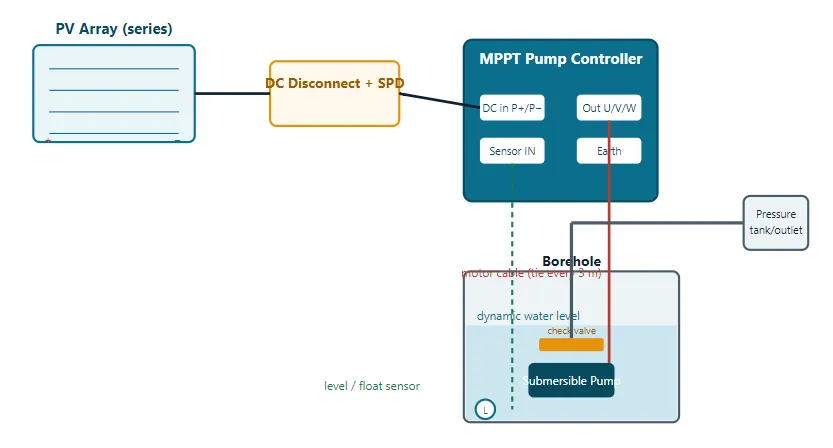
Figure 1 — Basic DC system: series PV array → DC disconnect + SPD → MPPT controller → submersible pump, with check valve and dry-run sensor.
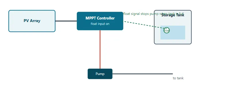
Figure 2 — Tank-level control: a float switch signals the controller to stop the pump when full and restart when demand lowers the level. Pumping by day into storage removes the need for batteries.
6. Cable sizing (keep voltage drop under 3%)
Undersized cable starves the motor and trips the controller. Use the manufacturer's table as primary; these are starting points by system voltage and one-way run length.
7. Commissioning test checklist
- Electrical:
Voc within ±5% of panel spec; polarity correct; earth resistance < 1 Ω; insulation > 1 MΩ; controller cool under load. - Hydraulic:
flow 85–105% of rated at measured TDH (bucket test: L/hr = litres × 3,600 ÷ seconds); pressure holds; check valve stops backflow; no leaks. - Baseline:
record date, weather, flow, voltage, current and pressure — your reference for future troubleshooting.
8. Troubleshooting common problems
Pump will not start
Measure PV voltage at the controller input (low means shade/dirty panels/broken string). Read the controller error code. Disconnect the pump and check winding resistance — open circuit = cable/motor fault; near-zero = shorted windings. Confirm the dry-run sensor is not holding the pump off.
Low flow
Re-measure TDH (drawdown is often higher than estimated). Inspect the check valve for blockage and the discharge valve for full opening. Check pump voltage — below ~90% of rated means oversized voltage drop from undersized cable. Listen for air in the discharge (a leak above the intake draws air).
Cycles on and off
Usually the well cannot keep up: reduce the pumping rate or add storage. Also check intermittent shading, loose or corroded connections, and controller thermal/voltage protection events in the log.
Cloudy or muddy water
Initial cloudiness after install is normal and clears in ~30 minutes. Persistent cloudiness means the pump is too close to the bottom (raise it 5–10 m) or the flow rate is pulling sediment (restrict flow, add a 5–20 µm filter).
Motor runs but no water
Lost prime (intake above water), a stuck-open check valve, a cracked drop pipe leaking back, or reversed rotation on a three-phase pump (swap two phases). Check current — a backwards pump draws noticeably less.
High current draw
Mechanical binding (worn bearings, impeller rubbing, foreign object), higher-than-designed head pressure, or high-resistance connections heating up. Measure with a clamp meter against the datasheet; pull and service the pump if mechanical.
9. Maintenance schedule
- Monthly:
clean panels, bucket-test flow, check for leaks, log voltage/current. Dirty panels can lose 20–30% output. - Quarterly:
water-quality check, inspect connections and grounding, test the check valve, measure static water level. - Annually:
full electrical test (insulation resistance), panel output check, re-torque mounting and terminals, inspect the controller for insects/moisture, review logs. - As needed:
descale the check valve and pump in hard/TDS water (every few years); service or replace the pump on flow decline.
10. Frequently asked questions
Q1. How deep can a solar submersible pump lift water?
Standard DC pumps reach 30–120 m; high-head and three-phase AC/VFD systems reach 200–300 m. The limit depends on motor power, stages, required flow and cable voltage drop — a pump lifted at lower flow reaches higher.
Q2. Can I install it myself?
Shallow wells (<30 m) and small (<750 W) DC systems are often DIY-friendly. Deep wells, high-power or three-phase systems, and drinking-water installs should be done or inspected by a qualified contractor, especially where codes require a licence.
Q3. What size array do I need?
Pump watts × 1.3–1.5 for losses — a 1,500 W pump needs ~2,000–2,250 Wp. Then confirm runtime from daily watt-hours divided by local peak sun hours and ~0.8 efficiency.
Q4. Does it work on cloudy days?
Yes, at reduced flow — an MPPT controller slows the pump to match available power (roughly 25–70% on overcast days). Oversize the array 30–50% and store 2–5 days of water to cover cloudy spells.
Q5. What if it runs dry?
The motor loses water cooling and can be damaged within minutes — seals, bearings and windings fail. A water-level sensor on the controller's dry-run input plus correct depth prevents it; the sensor costs a fraction of a pump replacement.
Q6. Can it supply drinking water?
Yes, with NSF/ANSI 61 rated components, potable-rated pipe, a sanitary seal, and appropriate treatment (filtration, UV) based on lab water tests.
Q7. How do I winterise it?
Where pipes freeze, bury surface pipe below the frost line or heat-trace it; for seasonal shutdown, drain all surface water, blow lines out with compressed air, and tilt panels steeply to shed snow. The pump itself sits below the frost line and is protected by the earth.
Bottom line
A solar submersible pump install is won before the pump enters the water: correct TDH-based sizing, panels in series through a proper DC disconnect and surge protector, a shaded grounded controller, correctly rated cable under 3% voltage drop, and the pump set at the right depth with a working dry-run sensor. Buy components that carry recognised certifications — IP68 on the motor, UL 778 or IEC/EN 60335-2-41 on the pump, IEC 62109 on the controller, NSF/ANSI 61 for drinking water — and have a qualified electrician sign off the final work. Done this way, the system delivers reliable off-grid water for a decade or more.
This guide is general educational material and does not replace the manufacturer's manual, local electrical code or water-well regulations. Component standards referenced: UL 778, NEC 690, IEC/EN 60335-2-41, IEC 62109, IEC 62253, IEC 60364, IEC 60529 (IP68), NSF/ANSI 61, CE, TÜV, MCS, ISO 9001. Always consult a licensed professional where required.